
News
Technical Note: To Deform or Not to Deform: That is the Question!
Flexible net rockfall catchment fences are one tool available to engineers for mitigating rockfall events. These systems have been in use for decades around the world with a rather impressive performance record. Though the basic concept of the systems has remained relatively unchanged during this time, the specifics of the fences have become more advanced, incorporating components that can accommodate large deformations and thus absorb large amounts of energy. In contrast, there has been a trend whereby the foundation designs have become more robust and most often entirely rigid, where even small deformations of the anchorage are not tolerated. This has led to rather large and expensive solutions for supporting an otherwise cost-efficient and flexible structure.
There is no doubt that by providing a rigid and unmovable foundation, one is providing as close a base state as to the conditions under which these systems are tested during certification. It more or less guarantees that the system will perform to a minimum standard. But it is not necessarily the case that this performance cannot be met or even exceeded by other means. In fact, it is often seen in natural events, where a more minimalistic approach to post base support is used, that a system exhibits performance well beyond the expected. This is often attributed to the fact that the base support showed significant deformation during the event, thereby absorbing excess energy. In these cases, it could be argued that should a rigid foundation have been used, the system would have failed at the system-foundation boundary or at some other internal point that would have been overloaded.
The usefulness of a “soft” foundation for post base support can be seen in an example from British Columbia where a barrier rated for a 1000 kJ was impacted multiple times by events much larger than its capacity (Fig 1). In this case, a very small concrete leveling pad was used (e.g. 15 x 15 x 49 inches) in combination with two soil anchors (R38N), drilled approximately 16 feet deep and with only partial grout return (Fig. 2). In two extreme cases, the fence was impacted directly at a post as seen in the photos. In the first impact, significant deformation of the foundation was noted (Fig. 3) but all debris was contained. After the event, the fence was repaired and a new post was set on the existing (damaged) post base support. A second, even larger, event occurred in an adjacent field and the system once again held, though in this case the impact completely destroyed the footing (Fig. 4). Even so, all of the debris was caught once again. In both cases, with current available design guidelines, it would have been impractical to design a foundation to perform to this level.
There are undoubtedly many other stories similar to this one from throughout the world. The AGHP’s Post Support Systems Committee is currently reaching out to engineers and owners that have experience with catchment fence foundation design, both good and bad, in order to synthesize an empirical summary of designs and their performance. Should you have interest in this project, please contact a.bichler@trumer.cc or tim.shevlin@geobrugg.com
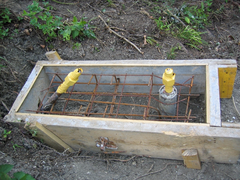
Figure 1: Impact into 1000 kJ fence protecting penstock.
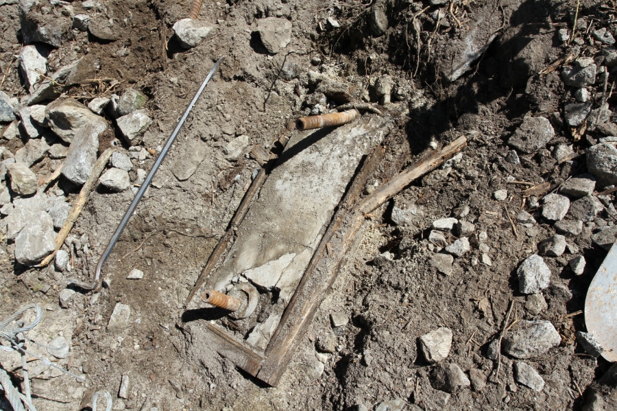
Figure 2: Example of simple post base support used for high energy rockfall catchment fences consisting of a small concrete pad, two soil anchors and a micropile tube.
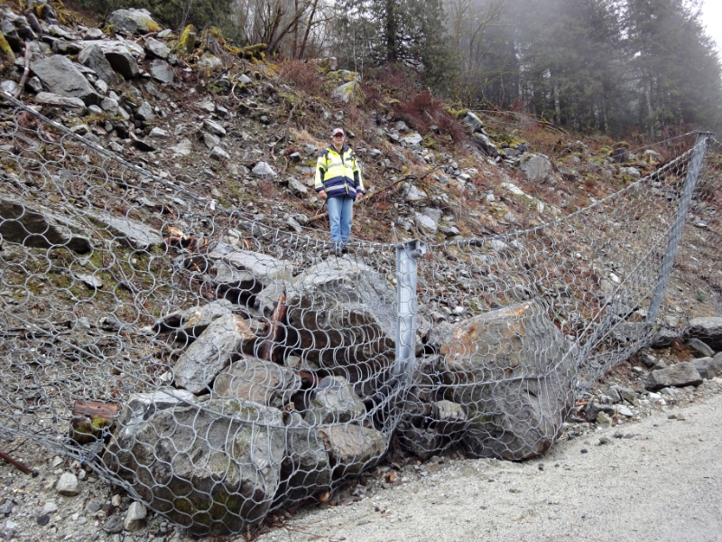
Figure 3: Photo showing the damage to the post base support following the event in Figure 1. The anchors have been slightly deformed and the concrete surrounding the micropile tube has been cracked. Total displacement of the post base support was on the order of an inch.
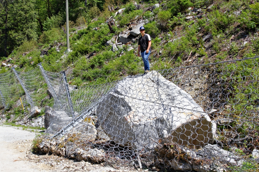
Figure 4: Second event impacting the same fence, in an adjacent field to the previous impact.